
Practice Drawing No.20
- Mech Surge

- Aug 16, 2020
- 2 min read
Updated: Jun 1, 2021
Open the Catia V5 application. The assembly workbench is opened it is default. Close the assembly workbench and Go to START--->MECHANICAL DESIGN---->PART DESIGN, Now enter the part name what you want and click the enable hybrid design checkbox and ok.
Select ZX plane in the specification tree and then choose sketch tool from the sketcher toolbar.
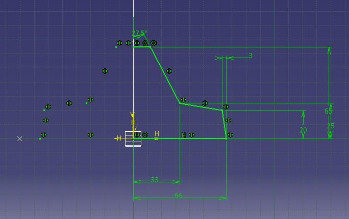
Select profile tool from profile toolbar and draw as shown in fig and constraint this.

Click exit workbench and select YZ axis. Select point and draw point as shown in fig.

And exit workbench.
Choose plane. Plane definition dialog box is opened. Select plane type as through three points and select the three points as shown in fig.

Now select the new plane in the specification tree and click exit workbench. Choose profile tool from profile toolbar as shown in fig. constraint this using constraint tool.
Click edit multi constraint tool and enter the actual dimension given in the drawing.
Select the sketches and click mirror tool and select vertical direction. After mirror the model is shown in fig.

Click exit workbench, part design workbench is invoked. Choose pad tool from sketch based feature and enter 14mm in the length spinner and click mirrored extend checkbox.

Click plane, plane definition dialog is opened. Select plane type as normal to curve. Now select the line which was drawn on first and click the endpoint of the line. Then click ok.

Select the newly drawn plane and click sketch tool.
Choose circle tool from profile toolbar. Draw as shown in fig. then click exit workbench.

Click drafted filleted pad tool from pad sub-toolbar. Drafted filleted pad definition dialog box is opened. Enter second limit is as XY plane and draft angle is 2deg, unclick the checkboxes of lateral radius, first limit radius and second limit radius and click ok.


Select the face of the model and click sketch. The sketcher workbench is invoked.
Select rectangle tool and draw as shown in fig and click exit workbench then choose pocket tool from sketch based feature toolbar and click reverse direction and then click ok.


Now select edge fillet tool enter 3mm in the radius and select the lines as shown in fig. then click ok.

Again select edge fillet tool and enter 12mm in the radius and select the lines as shown in fig. and click ok.

Pick shell tool, enter default inside thickness value is 2mm and select the face to remove faces as shown in fig then click ok.

The final model is shown in fig

WATCH VIDEO


Comments