
Practice Drawing No.35
- Mech Surge

- Sep 13, 2020
- 2 min read
Updated: May 23, 2021
Open the Catia V5 application. The assembly workbench is opened it is default. Close the assembly workbench and Go to START--->MECHANICAL DESIGN---->PART DESIGN, Now enter the part name what you want and click the enable hybrid design checkbox and ok.
Select YZ plane in the specification tree and then choose sketch tool from the sketcher toolbar.
Choose circle tool and line tool one by one and draw as shown in fig. and constraint this.

Now click exit workbench, choose plan tool. Plane definition dialog box is open. Select plan type as normal to curve. Select curve and select the end point and click ok.

Now select the newly created plan and click sketch. Choose circle tool and draw two circles in the diameter of 210 and 290 respectively as shown in fig and constrain this using constraint tool.

Click exit workbench, choose rib tool. Rib definition dialog box is open. Select profile in two circles then select the curve which was drawn initially and click ok.

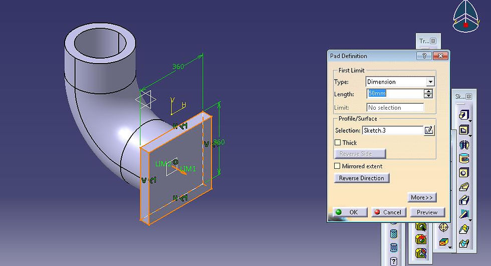
Select the face as shown in fig and click sketch. Choose centered rectangle and draw as shown in fig and constraint this using constraint tool. Click exit workbench.

Choose pad tool. Pad definition dialog box is open. Enter 50mm in the length and click ok.
Choose/select edge fillet tool. Edge fillet definition dialog box is open. Enter radius as 20mm and select the four edges as shown in fig and click ok. Now the model is shown in fig.

Now select face shown in fig and click sketch tool. . Choose centered rectangle and draw as shown in fig and constraint this using constraint tool. Click exit workbench.

Choose pad tool. Pad definition dialog box is open. Enter 50mm in the length and click ok.

Choose/select edge fillet tool. Edge fillet definition dialog box is open. Enter radius as 20mm and select the four edges as shown in fig and click ok. Now the model is shown in fig.

Choose hole tool. Hole definition dialog box is open. Select up to next and click ok.

Now choose rectangle pattern tool. Rectangle patter definition dialog box is open. Enter 2 in Instances, spacing- 260mm and click ok.

Again select rectangle pattern. Rectangle pattern definition dialog box is open. Enter 2 in Instances, spacing- 260mm and click ok. Change the direction of pattern towards down and click ok.

Do the same for make hole at the top rectangle face.
Select the face as shown in fig and click sketch tool. Choose circle tool, draw circle as shown in fig. and constraint this.

Click exit workbench, choose pocket tool. Pocket definition dialog box is open. Enter 50mm in the depth and click ok.

Select the face as shown in fig and click sketch tool. Choose circle tool, draw circle as shown in fig. and constraint this.

Click exit workbench, choose pocket tool. Pocket definition dialog box is open. Enter 50mm in the depth and click ok.

The final model is shown in fig.

WATCH VIDEO


Comments