
Practice Drawing No.33
- Mech Surge

- Sep 13, 2020
- 3 min read
Updated: May 23, 2021
Open the Catia V5 application. The assembly workbench is opened it is default. Close the assembly workbench and Go to START--->MECHANICAL DESIGN---->PART DESIGN, Now enter the part name what you want and click the enable hybrid design checkbox and ok.
Select YZ plane in the specification tree and then choose sketch tool from the sketcher toolbar.
Draw as shown in fig by choosing circle, three-point arc and line tool. Then choose translate tool, enter 5 in instances and click ok.

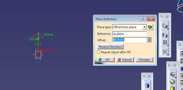
Click exit workbench, choose plan tool, select plan type as offset from plane, reference XY Plane and offset length is 47.5mm, then click ok.
Now select the new plane and click sketch.
Draw as shown in fig by choosing circle, three-point arc and line tool. Then choose translate tool, enter 5 in instances and click ok.

Click exit workbench, choose plan tool, select plan type as offset from plane, reference as Plane1 and offset length is 47.5mm, then click ok.

Draw as shown in fig by choosing circle, three-point arc and line tool. Then choose translate tool, enter 5 in instances and click ok.

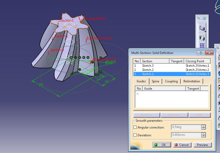
Click exit workbench, now choose multi section solid tool. Muto section solid definition dialog box is open, select the three sketches and click ok.
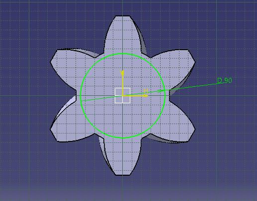
Select bottom face of the model and click exit workbench.
Choose circle tool and draw as shown in fig and constraint this.
Now click exit workbench, choose pad tool. Pad definition dialog box is open. Enter 5mm in the length spinner and click ok.


Now choose the bottom of the newly padded feature and click sketch tool.
Choose circle tool, draw as shown in fig and constraint this.

Now click exit workbench, choose pad tool. Pad definition dialog box is open. Enter 46mm in the length spinner and click ok.

Now choose the bottom of the newly padded feature and click sketch tool.
Choose circle tool, draw as shown in fig and constraint this.

Now click exit workbench, choose pad tool. Pad definition dialog box is open. Enter 10mm in the length spinner and click ok.

Now choose the bottom of the newly padded feature and click sketch tool.
Choose circle tool, draw as shown in fig and constraint this.

Now click exit workbench, choose pad tool. Pad definition dialog box is open. Enter 102mm in the length spinner and click ok.

Now choose the bottom of the newly padded feature and click sketch tool.
Choose circle tool, draw as shown in fig and constraint this.

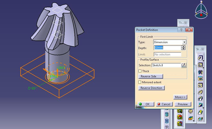
Now click exit workbench, choose pocket tool. Pocket definition dialog box is open. Enter 32mm in the length spinner and click ok.
Select zx plane and click sketch tool.
Draw circle as shown in fig and constraint this.

Click exit workbench, choose groove tool. Groove definition dialog box is open. Enter 360deg in first angle and click ok.

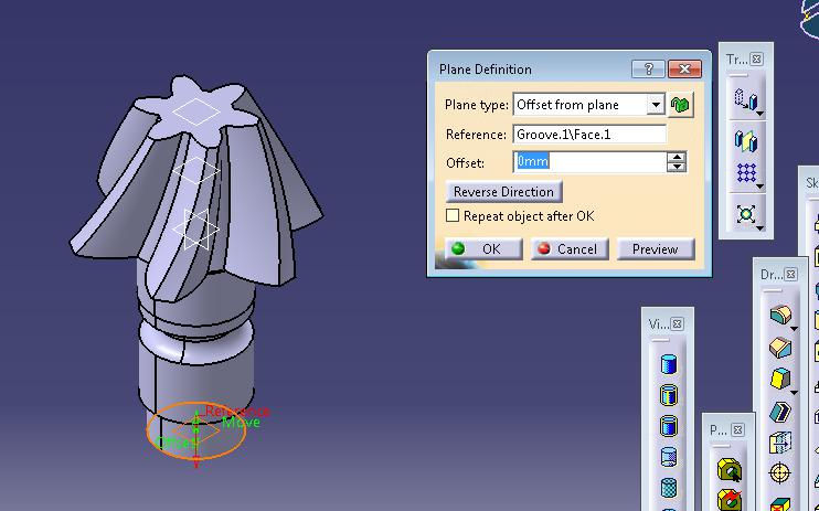
Now choose plan tool. Plane definition dialog box is open. Select plant type as offset from plane, select reference as groove1 and click ok.
Again choose plan tool. Plan definition dialog box is open. Select plan type as offset from plan, select reference newly drawn plan and click ok.

Select newly drawn plane and click sketch tool. Draw rectangle as shown in fig and constraint this.

Click exit workbench, choose pad tool. Pad definition dialog box is open. Enter 48mm in the length spinner and click ok.

Choose circular pattern tool. Circular pattern definition dialog box is open. Select complete crown in parameters. Enter instances as 12 and click ok.

The final model is shown in fig.

WATCH VIDEO


Comments