
Practice Drawing No.21
- Mech Surge

- Aug 16, 2020
- 2 min read
Updated: Jun 1, 2021
Open the Catia V5 application. The assembly workbench is opened it is default. Close the assembly workbench and Go to START--->MECHANICAL DESIGN---->PART DESIGN, Now enter the part name what you want and click the enable hybrid design checkbox and ok.
Select ZX plane in the specification tree and then choose sketch tool from the sketcher toolbar.
Choose profile tool from profile toolbar. Draw as shown in fig and constraint this using constraint tool. Now select the sketched element and click mirror tool, then select vertical direction (Y-Axis). The model after mirror is shown in fig.

Choose three point circle tool and draw as shown in fig and constraint this.

Click exit workbench, choose pad tool from sketch based toolbar. Pad definition dialog box is open. Enter 125mm in the length spinner.

Choose plane tool. Plan definition dialog box is open. Choose xy plane as reference, enter 28mm in offset and click ok.

Now select new plane from specification tree and click sketch.
Select the line as shown in fig, click construction/standard element tool and click project 3d element.
Choose rectangle, draw as shown in fig and constraint this. Click exit workbench.

Choose pad tool. Pad definition dialog box is open. Select type as up to next, click ok. The model is shown in fig.

Choose draft tool, draft definition dialog box is open. Enter 3deg in angle;in faces to draft select the side faces as shown in fig. select bottom face for selection in neutral element and click ok.

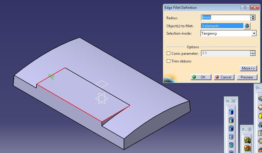
Choose edge fillet tool. Edge fillet definition dialog box is open. Enter 3mm in radius and select the edges ass shown in fig and click ok.
Again select edge fillet and select the line as shown in fig. enter 1mm in radius and click ok.

Click shell tool. Shell definition dialog box is open. Enter 2mm in default inside thickness. Select bottom face as shown in fig in face to remove and click ok. After shell the model is shown in fig.

Select yz plane from specification tree and click sketch tool. Select line as shown in fig and click construction/element tool and click project 3d element. Then unclick the construction/standard element tool.
Choose profile tool, then draw as shown in fig and constraint this.

Now click exit workbench. Choose pocket tool. Pocket definition dialog box is open. Enter125mm in depth and select mirrored extend, then click ok.

Select zx plane from specification tree and click sketch, Select line as shown in fig and click construction/element tool and click project 3d element. Then unclick the construction/standard element tool.
Choose profile tool and draw as shown in fig and constraint this. Then click exit workbench.

Choose pocket tool. Pocket definition dialog box is open. Enter150mm in depth and select mirrored extend, then click ok.

The final model is shown in fig.

WATCH VIDEO


Comments