
Practice Drawing No.22
- Mech Surge

- Aug 16, 2020
- 2 min read
Updated: Jun 1, 2021

Open the Catia V5 application. The assembly workbench is opened it is default. Close the assembly workbench and Go to START--->MECHANICAL DESIGN---->PART DESIGN, Now enter the part name what you want and click the enable hybrid design checkbox and ok.
Select XY plane in the specification tree and then choose sketch tool from the sketcher toolbar.
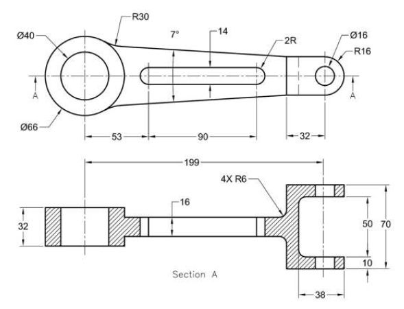
Choose circle tool from profile toolbar. Draw two circles and constraint this as shown in fig.

Click exit workbench. Choose pad tool from sketch based feature. Pad definition dialog box is open. Enter 16mm in the length spinner and click mirrored extend tool. Then click ok.

Choose YZ plane from specification tree and click sketch tool. Choose point tool from profile toolbar and draw point as shown in fig then constraint this.

Choose profile tool. Draw as shown in fig and constraint this. Now select the sketched element, click mirror tool and click horizontal direction (X-axis).

Click exit workbench. Choose pad tool. Pad definition dialog box is open. Enter16mm in the length spinner and click mirrored extend check-box and then click ok.

Select face as shown in fig and click sketch tool. Choose circle tool. Draw as shown in fig and constraint this. Now select the line as shown in fig. click construction/standard element tool and click project 3d element.

Now choose profile tool. Draw lines as shown in fig choose quick trim tool and remove the unwanted lines and click exit workbench.
Choose pad tool. Pad definition dialog box is open. Enter 10mm in the length spinner and click ok.
Now select the face as shown in fig and click mirror tool. Mirror definition dialog box is open. Select xy plane in specification tree in mirroring element and click ok. Now the model is shown in fig.

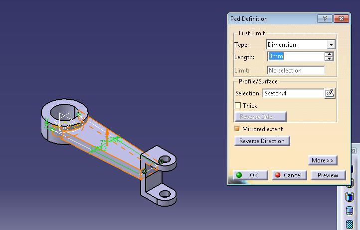
Select xy plane and click sketch. Draw as shown in fig using circle and bi-tangent line tool. Click exit workbench.

Choose pad tool. Pad definition dialog box is open. Enter 8mm in the length spinner and click mirrored extend checkbox, and then click ok.
Choose edge fillet tool. Edge fillet definition dialog box is open. Enter 30mm in the radius and select the lines as shown in fig.

Again choose edge fillet tool. Edge fillet definition dialog box is open. Enter 6mm in the radius and select the lines as shown in fig and click ok. Now the model is shown in fig.

Choose elongated hole tool and draw as shown in fig. click exit workbench.

Choose pocket tool. Pocket definition dialog box is open. Select up to next in type and click ok.

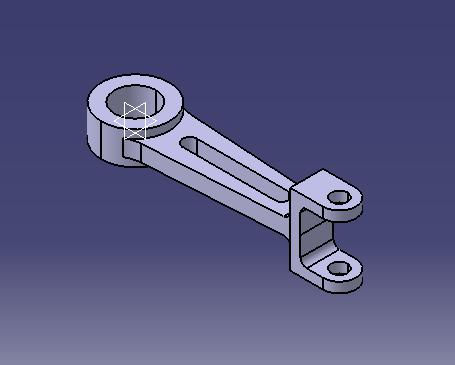
The final model is shown in fig.
WATCH VIDEO


Comments