
Practice Drawing No.26
- Mech Surge

- Sep 5, 2020
- 2 min read
Updated: May 23, 2021
Open the Catia V5 application. The assembly workbench is opened it is default. Close the assembly workbench and Go to START--->MECHANICAL DESIGN---->PART DESIGN, Now enter the part name what you want and click the enable hybrid design checkbox and ok.
Select YZ plane in the specification tree and then choose sketch tool from the sketcher toolbar.
Choose rectangle; draw as shown in fig and constraint this.

Click exit workbench, choose pad tool. Pad definition dialog box is open. Enter 12mm in the length spinner, then click ok.

Choose edge fillet tool, edge fillet definition dialog box is open. Enter 10mm in radius. Select edges as shown in fig. and click ok.

Select front face of the pad1 feature. Chose circle tool and draw as shown in fig and constraint this.

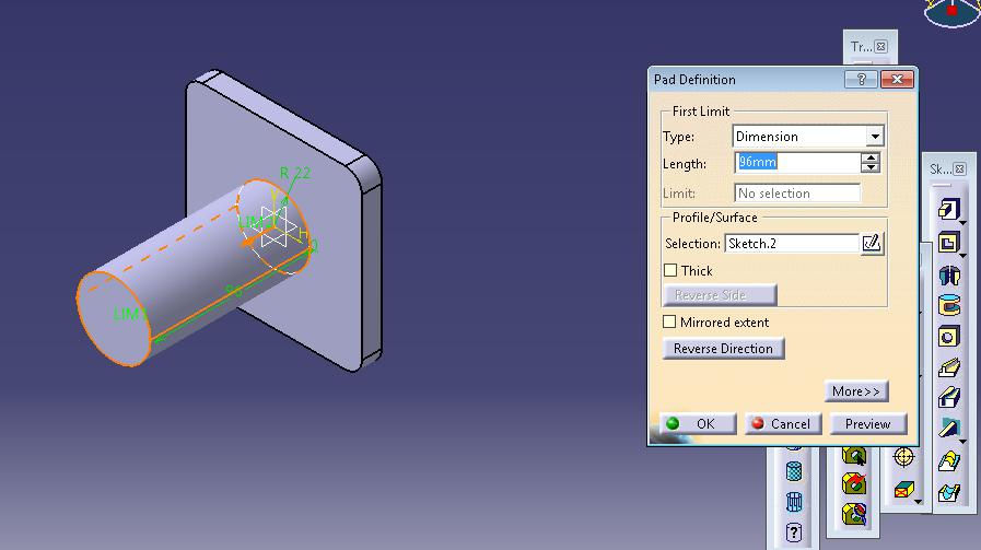
Click exit workbench, choose pad tool, pad definition dialog box is open. Enter 96mm in the length spinner and click ok.
Select front face of the pad2 feature, click sketch tool. Draw as shown in fig by using circle and profile tool. Constraint this.

Click exit workbench, choose pad tool. Pad definition dialog box is open. Enter 76mm in the length spinner and click ok.

Select front face of the pad2 feature and click sketch tool. Click exit workbench, choose pad tool. Pad definition dialog box is open. Enter 57mm in the length spinner and click ok.

Now choose/select face as shown in fig and click sketch. Choose rectangle tool, draw as shown in fig and constraint this.

Click exit workbench, choose pocket tool. Pocket definition dialog box is open. Enter 57mm in the depth and click ok.

Choose hole tool. Hole definition dialog box is open. Enter diameter as 35mm, depth 82mm. select V-Bottoma and enter 90 deg angle and click ok.

Again choose hole tool. Hole definition dialog box is open. Enter diameter as 12mm, depth 22mm and click ok.

Again choose hole tool. Hole definition dialog box is open. Enter diameter as 12mm, depth 22mm and click ok.

Choose hole tool. Hole definition dialog box is open. Enter diameter as 10mm, depth 22mm and click ok.

Choose hole tool. Hole definition dialog box is open. Enter diameter as 10mm, depth 22mm and click ok.

Choose hole tool. Hole definition dialog box is open. Enter diameter as 10mm, select up to next.

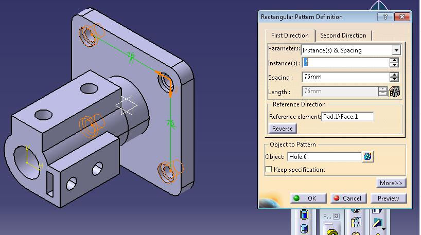
Choose rectangle pattern. Rectangle pattern definition dialog box is open. Enter 2 instances, select pad1 feature and click ok.
Choose edge fillet tool. Edge fillet definition dialog box is open. Enter 5mm in radius and select 2 lines as shown in fig and click ok.

The final model is shown in fig.

WATCH VIDEO


Comments