
Practice Drawing No.29
- Mech Surge

- Sep 5, 2020
- 2 min read
Updated: May 23, 2021
Open the Catia V5 application. The assembly workbench is opened it is default. Close the assembly workbench and Go to START--->MECHANICAL DESIGN---->PART DESIGN, Now enter the part name what you want and click the enable hybrid design checkbox and ok.
Select XY plane in the specification tree and then choose sketch tool from the sketcher toolbar.
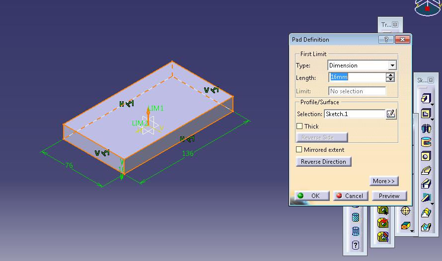
Choose rectangle tool. Draw as shown in fig and constraint this.

Click exit workbench, choose pad tool. Pad definition dialog box is open. Enter 16mm in the length spinner and click ok.
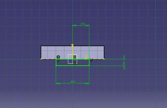
Select side face of the pad1 feature ad click sketch tool.
Now select rectangle tool and draw as shown in fig. click exit workbench, choose pad tool. Enter 136mm in the length spinner and click ok.

Again select side face of the pad1 feature and click sketch tool. Draw as shown in fig by using circle and line tool.
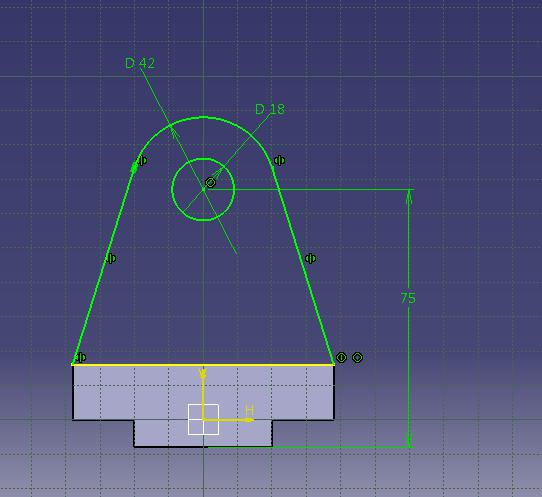
Click exit workbench, choose pad tool. Pad definition dialog box is open. Enter 16mm in the length spinner and click ok.

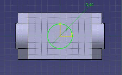
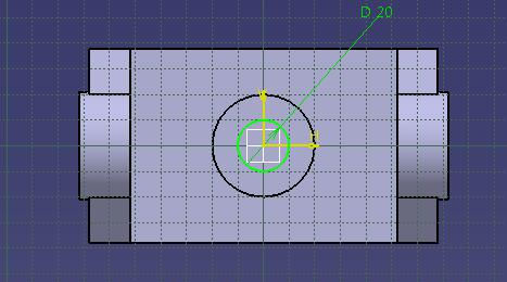
Now select pad3 feature side face and click sketch tool. Choose circle tool and draw as shown in fig and constraint this.

Click exit workbench, choose pad tool. Pad definition dialog box is open. Enter 4mm in the length spinner and click ok.

Now choose mirror tool and select YZ plane the model after mirror is shown in fig.

Select top face of the pad1 feature. Choose circle tool. Draw as shown in fig. and constraint this.
Click exit workbench, choose pad tool. Pad definition dialog box is open. Enter 2mm in the length spinner and click ok.

Now select the circle which was padded lastly and click sketch tool.
Choose circle tool. Draw as shown in fig. and constraint this.
Click exit workbench, choose pocket tool. Pocket definition dialog box is open. Select type as up to next and click ok.

The final model is shown in fig.

WATCH VIDEO


Comments