
Practice Drawing No.32
- Mech Surge

- Sep 13, 2020
- 2 min read
Updated: May 23, 2021
Open the Catia V5 application. The assembly workbench is opened it is default. Close the assembly workbench and Go to START--->MECHANICAL DESIGN---->PART DESIGN, Now enter the part name what you want and click the enable hybrid design checkbox and ok.
Select YZ plane in the specification tree and then choose sketch tool from the sketcher toolbar.
Draw two circles as shown in fig and constraint this.

Click exit workbench, choose pad tool. Pad definition dialog box is open. Enter 16mm in the length spinner, click mirrored extend checkbox and click ok.

Now select front face of the pad1 feature and click sketch. Draw circles as shown in fig and constraint this.

Click exit workbench, choose pad tool. Pad definition dialog box is open. Enter 16mm in the length spinner, click mirrored extend checkbox and click ok.

Choose circular pattern tool. Circular pattern dialog box is open. Enter 6 in the instances,60deg in angular spacing and click ok.

Choose circle tool, draw as shown in fig. and constraint this.

Click exit work bench. Choose pocket tool. Pocket definition dialog box is open. Select type as up to next and click ok.

Choose circular pattern tool. Circular pattern dialog box is open. Enter 6 in the instances,60deg in angular spacing and click ok.

Select front face of the pad1 feature and click sketch.
Draw circles as shown in fig and constraint this.

Click exit work bench, choose pad tool. Pad definition dialog box is open. Enter 16mm in the length spinner, click mirrored extend check-box and click ok.

Again select the front face, draw as shown in fig and constraint this.

Click exit workbench, choose pad tool. Pad definition dialog box is open. Enter 11mm in the length spinner, click mirrored extend checkbox and click ok.

Again select the front face, draw as shown in fig and constraint this.
Click exit workbench, choose pad tool. Pad definition dialog box is open. Enter 11mm in the length spinner, click mirrored extend checkbox and click ok.

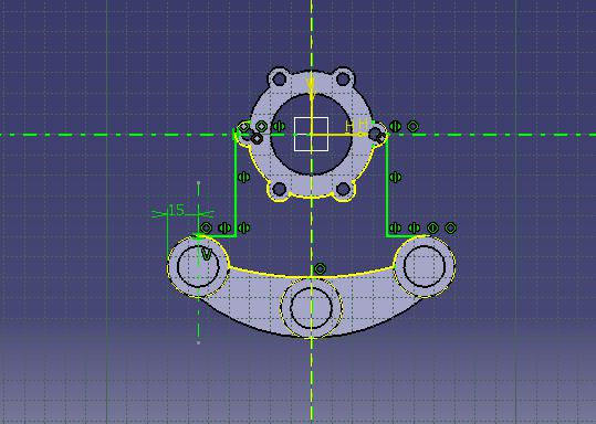
Again select the front face, draw as shown in fig and constraint this.

Click exit workbench, choose pocket tool. Pocket definition dialog box is open. Select up to next in type and click ok.

Choose edge fillet tool. Edge fillet definition dialog box is open. Entern18mm in the rad and select mode as tangency and click ok.

Choose edge fillet tool. Edge fillet definition dialog box is open. Entern18mm in the rad and select mode as tangency and click ok.

The final model is shown fig

WATCH VIDEO


Comments